Case Study
PFAS Remediation Design for Fire Training Site

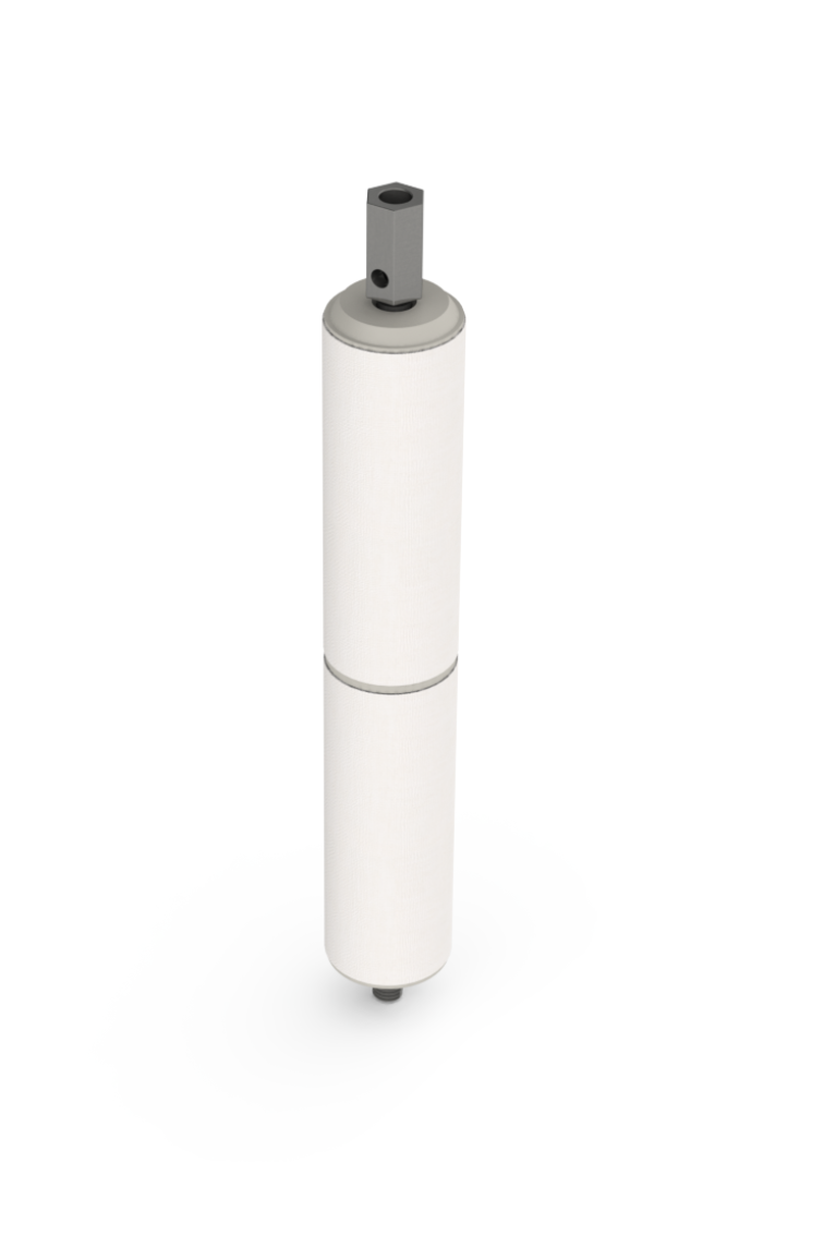
iFLUX Sampler
PFAS
Urban
Regenesis, mott macdonald
United kingdom
Our value
High spreading risk of PFAS contamination
Design PFAS barrier and measure its efficiency
Optimize liquid carbon injections depths by identifying high flux zones.
Situation
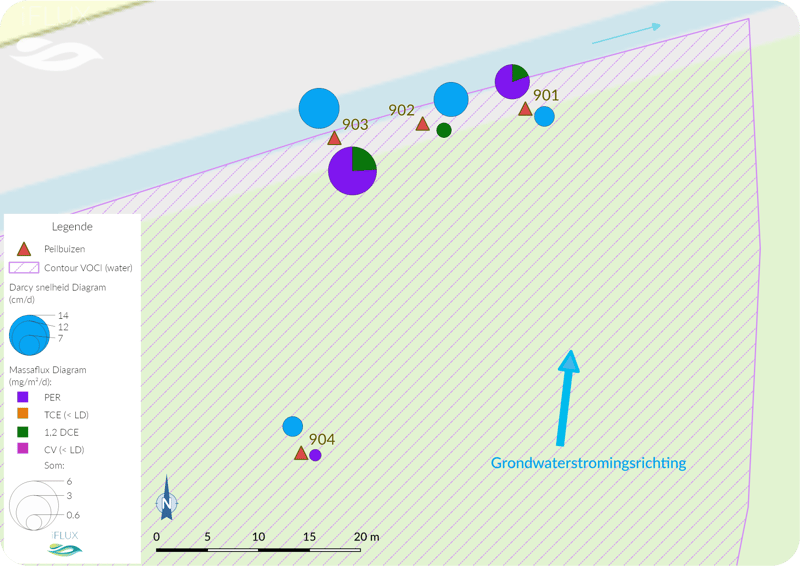
iFLUX has been mandated to carry out PFAS mass flux measurements on a site impacted by a PFAS pollution and for which a treatment is in progress.
The contamination was characterized and delineated in earlier soil survey. Additional flux measurements are used to design the barrier to prevent a PFAS pollution from spreading with the groundwater flow. Based on mass flux measurements the amount of liquid Activated Carbon to inject at different depths is calculated.
The soil is heterogeneous with gravely to sandy layers, calcareous clay, occasionally with shell fragments and at depth mudstone.
Sampling
Mass flux measurements are executed at several depths in two existing wells (diameter 51/63 mm). The wells are sampled. Mass flux measurement are performed to assess the potential stratification of PFAS fluxes in groundwater due to large differences in hydraulic conductivity of the different soil layers. The measurements cover the zones of high to medium hydraulic conductivity as well as a zone of lower conductivity, identified based on available HPT profiles. In total mass flux measurements are executed at 6 depths.

"Use of iFLUX allows for more accurate PlumeStop designs and increases the likelihood of groundwater treatment success"
Challenges
How to avoid PFAS from spreading:
- How to limit plume expansion of persistent and mobile contaminant?
- Injection is expensive
- Is active barrier effective?
- Large, dilute plumes (> 1 mile in length, 75% of plume is < 10µg/l)
The Solutions
The PFAS cartridge in collaboration with Cyclopure to optimize remedial design and measure its effectiveness:
- Flux measurements to optimize focused injection on high flux zones
- More efficient use of liquid activated carbon based on measured data
- Pro-active follow-up with flux measurements
- iFLUX PFAS cartridges has a detection limit of 5-10µg/m²/day and 5-80 ng/l and measures accumulation over time.
The Result
As expected, the highest PFAS fluxes were measured at depths corresponding to the targeted thinner soil layers of higher hydraulic conductivity, as identified by the HPT measurements, at depths around 3 mbgl, 5 mbgl, 6 mbls and 11 mbgl.
In the layer of lower hydraulic conductivity between 5m and 6m-bgl, the PFAS flux was significantly lower.
Averaged seepage velocities can be estimated based on the measured mass flux and groundwater concentration data. Depending on the substance, estimated averaged seepage velocities range from 20 to 70m/yr for the low hydraulic conductivity zone (between 5 and 6 m-bgl) and from 60 to 120 m/yr for the higher hydraulic conductivity zones.

A second measurement campaign is planned, after installation of the barrier. Upstream a monitoring of the Mass flux in one or two zones of higher hydraulic conductivity and with a higher PFAS flux, as well at 11 mbgl is planned.
To evaluate the barrier on longer term flux measurements downstream of the barrier can be of added value.
See how iFLUX will help your project.
Get in touch to review how the iFLUX Sampler will support your project.